Preparing to Drill
Once the site has been selected, it must be surveyed to determine its boundaries, and environmental impact studies may be done. Lease agreements, titles and right-of way accesses for the land must be obtained and evaluated legally. For off-shore sites, legal jurisdiction must be determined.
Once the legal issues have been settled, the crew goes about preparing the land:
- The land is cleared and leveled, and access roads may be built.
- Because water is used in drilling, there must be a source of water nearby. If there is no natural source, they drill a water well.
- They dig a reserve pit, which is used to dispose of rock cuttings and drilling mud during the drilling process, and line it with plastic to protect the environment. If the site is an ecologically sensitive area, such as a marsh or wilderness, then the cuttings and mud must be disposed offsite — trucked away instead of placed in a pit.
Once the land has been prepared, several holes must be dug to make way for the rig and the main hole. A rectangular pit, called a cellar, is dug around the location of the actual drilling hole. The cellar provides a work space around the hole, for the workers and drilling accessories. The crew then begins drilling the main hole, often with a small drill truck rather than the main rig. The first part of the hole is larger and shallower than the main portion, and is lined with a large-diameter conductor pipe. Additional holes are dug off to the side to temporarily store equipment — when these holes are finished, the rig equipment can be brought in and set up.
Setting Up The Rig
Depending upon the remoteness of the drill site and its access, equipment may be transported to the site by truck, helicopter or barge. Some rigs are built on ships or barges for work on inland water where there is no foundation to support a rig (as in marshes or lakes). Once the equipment is at the site, the rig is set up. Here are the major systems of a land oil rig:
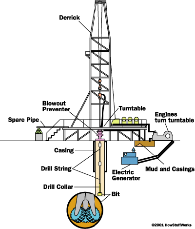
Anatomy of an Oil Rig
- Power system
- large diesel engines – burn diesel-fuel oil to provide the main source of power.
- electrical generators – powered by the diesel engines to provide electrical power.
- Mechanical System – driven by electric motors
- hoisting system – used for lifting heavy loads; consists of a mechanical winch (drawworks) with a large steel cable spool, a block-and-tackle pulley and a receiving storage reel for the cable.
- turntable – part of the drilling apparatus.
- Rotating equipment – used for rotary drilling.
- swivel – large handle that holds the weight of the drill string; allows the string to rotate and makes a pressure-tight seal on the hole.
- kelly – four or six-sided pipe that transfers rotary motion to the turntable and drill string.
- turntable or rotary table – drives the rotating motion using power from electric motors.
- drill string – consists of drill pipe (connected sections of about 30 ft/ 10 m) and drill collars (larger diameter, heavier pipe that fits around the drill pipe and places weight on the drill bit).
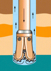
- drill bit(s) – end of the drill that actually cuts up the rock; comes in many shapes and materials (tungsten carbide steel, diamond) that are specialized for various drilling tasks and rock formations.
- Casing – large-diameter concrete pipe that lines the drill hole, prevents the hole from collapsing, and allows drilling mud to circulate.
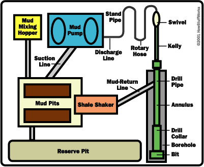
- Circulation system – pumps drilling mud (mixture of water, clay, weighting material and chemicals, used to lift rock cuttings from the drill bit to the surface) under pressure through the kelly, rotary table, drill pipes and drill collars.
- pump – sucks mud from the mud pits and pumps it to the drilling apparatus.
- pipes and hoses – connects pump to drilling apparatus.
- mud-return line – returns mud from hole.
- shale shaker – shaker/sieve that separates rock cuttings from the mud.
- shale slide – conveys cuttings to the reserve pit.
- reserve pit – collects rock cuttings separated from the mud.
- mud pits – where drilling mud is mixed and recycled.
- mud-mixing hopper – where new mud is mixed and then sent to the mud pits.
- Derrick – support structure that holds the drilling apparatus; tall enough to allow new sections of drill pipe to be added to the drilling apparatus as drilling progresses.
- Blowout preventer – high-pressure valves (located under the land rig or on the sea floor) that seal the high-pressure drill lines and relieve pressure when necessary to prevent a blowout (uncontrolled gush of gas or oil to the surface, often associated with fire).
Blowouts and Fires
In the movies, you see oil gushing (a blowout ), and perhaps even a fire, when drillers reach the final depth. These are actually dangerous conditions, and are (hopefully) prevented by the blowout preventer and the pressure of the drilling mud. In most wells, the oil flow must be started by acidizing or fracturing the well.
New Drilling Technologies
The U.S. Department of Energy and the oil industry are working on new ways to drill oil, including horizontal drilling techniques, to reach oil under ecologically-sensitive areas, and using lasers to drill oil wells.
Drilling
The crew sets up the rig and starts the drilling operations. First, from the starter hole, they drill a surface hole down to a pre-set depth, which is somewhere above where they think the oil trap is located. There are five basic steps to drilling the surface hole:
- Place the drill bit, collar and drill pipe in the hole.
- Attach the kelly and turntable and begin drilling.
- As drilling progresses, circulate mud through the pipe and out of the bit to float the rock cuttings out of the hole.
- Add new sections (joints) of drill pipes as the hole gets deeper.
- Remove (trip out) the drill pipe, collar and bit when the pre-set depth (anywhere from a few hundred to a couple-thousand feet) is reached.
Once they reach the pre-set depth, they must run and cement the casing — place casing-pipe sections into the hole to prevent it from collapsing in on itself. The casing pipe has spacers around the outside to keep it centered in the hole.
The casing crew puts the casing pipe in the hole. The cement crew pumps cement down the casing pipe using a bottom plug, a cement slurry, a top plug and drill mud. The pressure from the drill mud causes the cement slurry to move through the casing and fill the space between the outside of the casing and the hole. Finally, the cement is allowed to harden and then tested for such properties as hardness, alignment and a proper seal.
Drilling continues in stages: They drill, then run and cement new casings, then drill again. When the rock cuttings from the mud reveal the oil sand from the reservoir rock, they may have reached the final depth. At this point, they remove the drilling apparatus from the hole and perform several tests to confirm this finding:
- Well logging – lowering electrical and gas sensors into the hole to take measurements of the rock formations there.
- Drill-stem testing – lowering a device into the hole to measure the pressures, which will reveal whether reservoir rock has been reached.
- Core samples – taking samples of rock to look for characteristics of reservoir rock.
Once they have reached the final depth, the crew completes the well to allow oil to flow into the casing in a controlled manner. First, they lower a perforating gun into the well to the production depth. The gun has explosive charges to create holes in the casing through which oil can flow. After the casing has been perforated, they run a small-diameter pipe ( tubing ) into the hole as a conduit for oil and gas to flow up the well. A device called a packer is run down the outside of the tubing. When the packer is set at the production level, it is expanded to form a seal around the outside of the tubing. Finally, they connect a multi-valved structure called a Christmas tree to the top of the tubing and cement it to the top of the casing. The Christmas tree allows them to control the flow of oil from the well.
Once the well is completed, they must start the flow of oil into the well. For limestone reservoir rock, acid is pumped down the well and out the perforations. The acid dissolves channels in the limestone that lead oil into the well. For sandstone reservoir rock, a specially blended fluid containing proppants (sand, walnut shells, aluminum pellets) is pumped down the well and out the perforations. The pressure from this fluid makes small fractures in the sandstone that allow oil to flow into the well, while the proppants hold these fractures open. Once the oil is flowing, the oil rig is removed from the site and production equipment is set up to extract the oil from the well.
Extracting the Oil
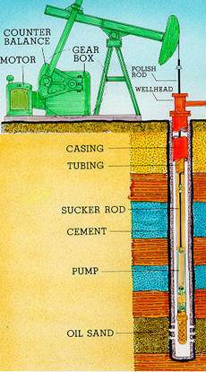
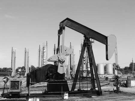
After the rig is removed, a pump is placed on the well head.
In some cases, the oil may be too heavy to flow. A second hole is then drilled into the reservoir and steam is injected under pressure. The heat from the steam thins the oil in the reservoir, and the pressure helps push it up the well. This process is called enhanced oil recovery.
In the pump system, an electric motor drives a gear box that moves a lever . The lever pushes and pulls a polishing rod up and down. The polishing rod is attached to a sucker rod , which is attached to a pump . This system forces the pump up and down, creating a suction that draws oil up through the well.


